Horizontal Stabilization of A Flexible Platform
In this work, we consider a four-legged leveling platform and develop a control strategy to automatically orient the platform to correct roll and pitch angle errors assuming the vehicle was initially situated on a sloping terrain. For this purpose, an FE model is constructed followed by a two-level control system with its hyperparameters tuned in repeated simulations.
Redundancy in critical systems is often desirable as it improves overall robustness. As such, four-legged systems are capable of carrying higher loads and also resist overturn.
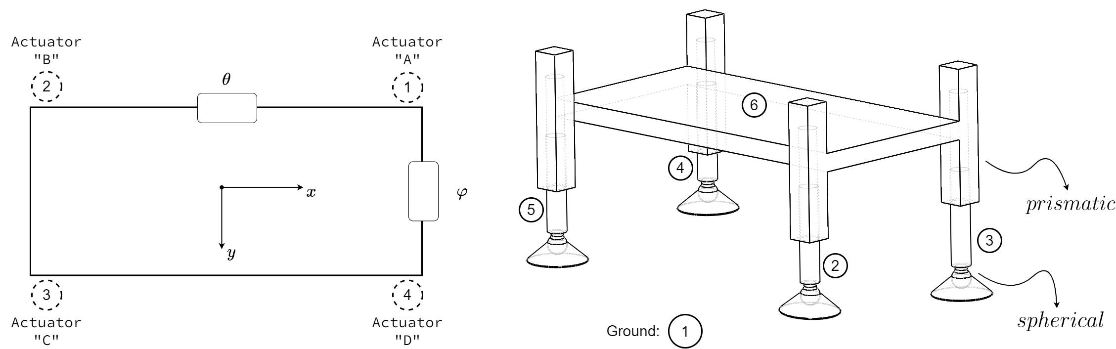
According to the structural model, all linear actuators are oriented perpendicular to the main frame. Actuators are modelled as prismatic joints while the connection between rods and foots are abstracted as spherical joints.
This system has -2 degrees-of-freedom: platform is structurally locked (negative value for degrees of freedom signifies an overstructured mechanism) and, as stated earlier, system motion is realized through deformation of flexible parts (chassis) in the system. In the following figure, as we impose kinematic displacement on the actuators, flexible members of the system begin to deform.
Finite-element model is constructed in ABAQUS while the controller is implemented in SIMULINK. To connect these software components, we use FMU-based Co-Simulation to perform a coupled simulation.
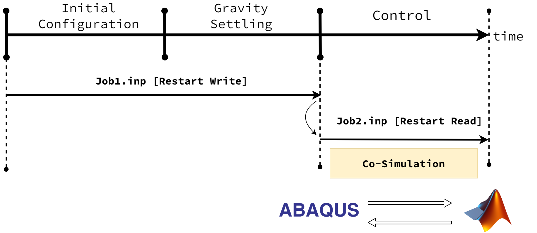
Simulation is carried out in three major steps as outlined below and shown in the following figure.
- Initial Configuration
- Gravitational Settling (Static Analysis)
- Control (Dynamic Analysis)
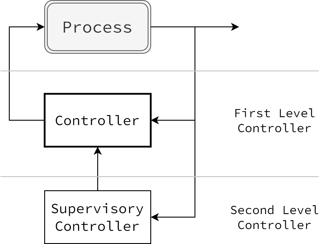
Control strategy is implemented in a hierarchical structure where two control loops are embedded in a multi-level control system and work in concert to achieve control objectives. The main control loop (low-level) is the primary computational unit that implements the main logic of leveling operation. High-level control loop acts a supervisory controller by monitoring the overall condition of operation and environmental variables and enforcing transition between various control modes.
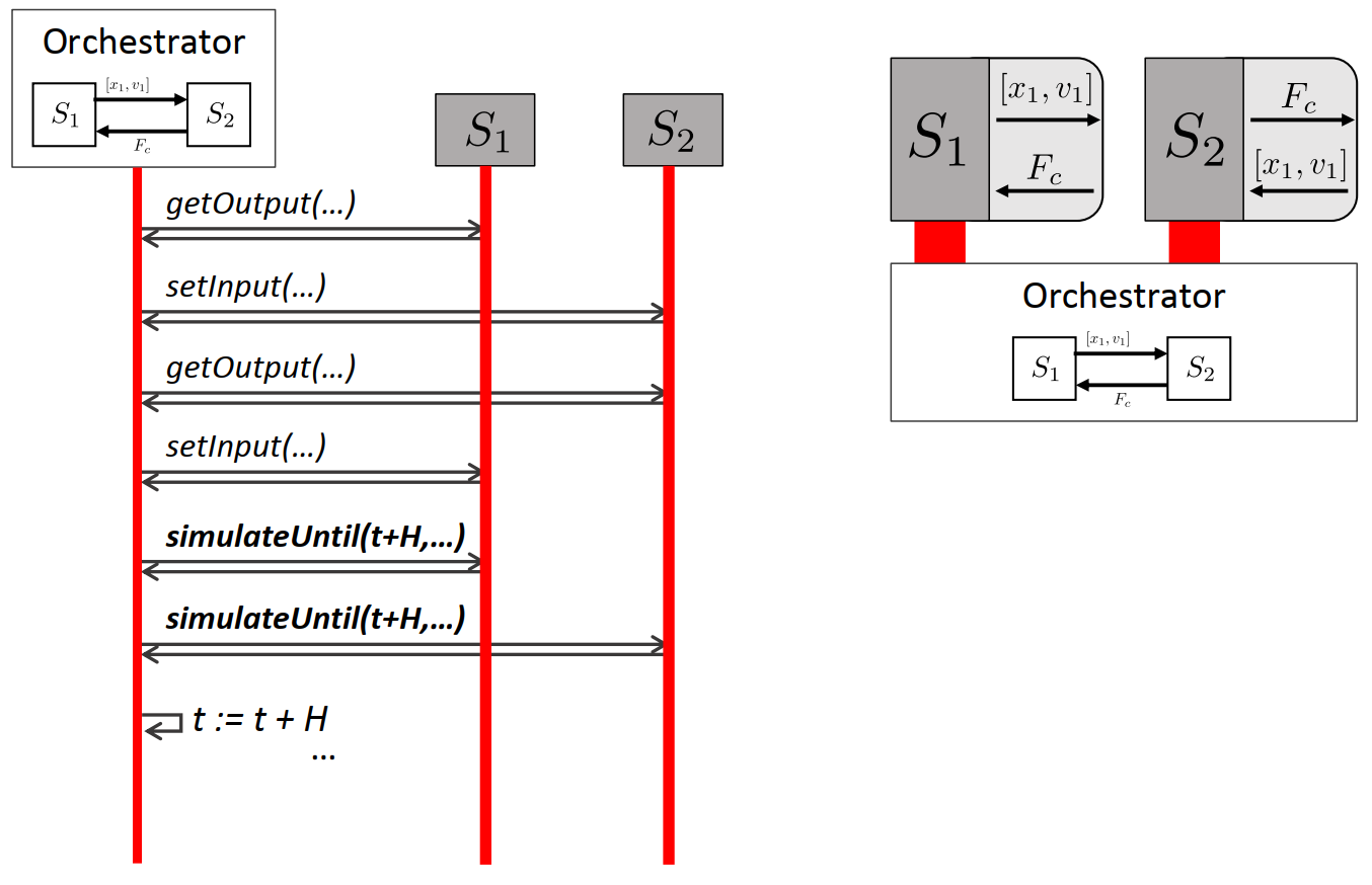
Abaqus uses the SIMULIA Co-Simulation Engine Director (CSE) as a software component for controlling a co-simulation. Specifically, it is in charge of coordinating and synchronizing execution and communication between all clients involved in the co-simulation. According to Abaqus documentation, CSE can be used to execute a structural-to-logical co-simulation between a Functional Mockup Unit (FMU) subsystem (as a logical component) and a Abaqus subsystem (as a structural component). FMI supports (a) sharing (exchange) of dynamic models (FMU-ME), and (b) co-simulation of dynamic models via the transfer of solution results from one dynamic model as input to one or more other dynamic models (FMU-CS). With FMI-ME, the FMU does not contain a solver. Instead, the solver is provided by the tool which imports and assembles the overall system model. A single solver can be used for multiple FMUs. The joint simulation is therefore not a co-simulation. The co-simulation solution approach is used when multiple dynamic models associated with different engineering disciplines are used to simulate a time-dependent coupled system or subsystem. In this case, the models associated with each particular discipline are solved each by their respective solvers in a distributed way during runtime.
Simulink models can be exported as a special form of FMU objects known as Tool-Coupling FMU. When Simulink-exported FMU and Abaqus job are connected to CSE, Simulink editor and Simulink project are loaded, and co-simulation starts automatically. This session can be used to pause, resume co-simulation, as well as tune parameters or plot signals from the command window while co-simulation is running. Various parameters must be configured for proper execution of co-simulation. Notably, coupling scheme and rendezvousing scheme should be carefully selected since they have significant impact on simulation quality and results. "Minimum-Timestep" and "Gauss-Seidel" methods are used for rendezvous and coupling scheme, respectively. Following figure shows the overall structure for a co-simulation.